
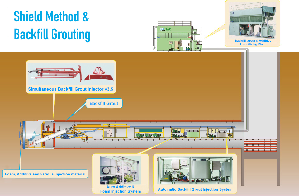
Backfill grout injection in shield tunneling is a construction method used to quickly fill the voids, called tail voids, that are generated between the segments and the ground during shield advance. In shield tunneling, excavation is carried out while preventing ground collapse with a shield machine, and steel or concrete segments are assembled in rings to form the tunnel lining. By promptly filling the tail voids, backfill grout injection fixes the segments in place and prevents ground settlement and adverse effects on surrounding structures.
In 1976, TAC developed the world's first two-component clay-sand backfill grout method, the "TAC Method."The NEO-TAC method is a two-component plastic backfill grout injection method that, in addition to the conventional TAC Method's characteristics—such as pseudo-solidified backfill injection that is not easily diluted by water, early strength development, and reliable filling performance—also achieves improved long-distance pumpability, enhanced long-term stability, and extended usable time (delayed setting) by adjusting the air content in Component A to 10–15%.
Benefits in construction
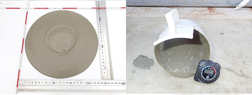
Backfill material tests (flow value, gel time, uniaxial compression test)
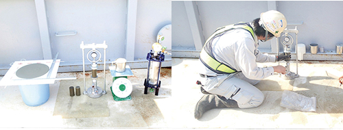
Backfill A-liquid volumetric change confirmation test
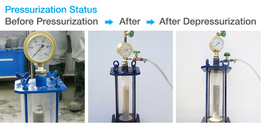
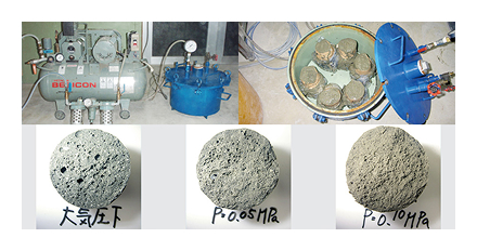
Pressurized curing test
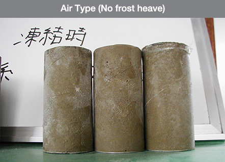
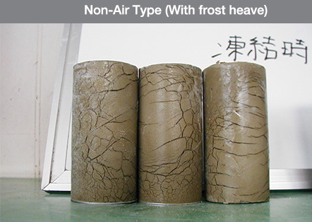
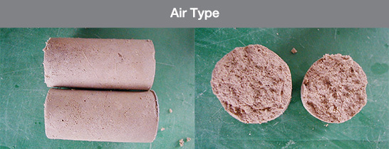
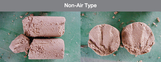
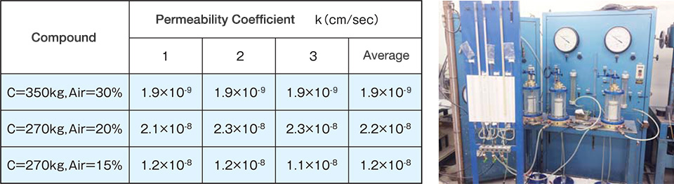
Before injection, air-based backfill materials offer excellent fluidity and resistance to material segregation, and during injection their high workability ensures excellent filling performance even into narrow tail voids. After injection, they develop strength at an early stage. Over the long term, they exhibit a low coefficient of permeability of 10⁻⁸ cm/sec or less, with superior thermal insulation performance and excellent resistance to freeze–thaw cycles.
Condition of frozen sections
During thawing
After thawing
Measurement of coefficient of permeability
Measured values from permeability tests using a triaxial cell
Here we introduce a lineup of high-performance backfill grout materials that can be selected according to the construction environment and project objectives.
| Material | Item Name | Packing | Specific Gravity | Intended Use |
|---|---|---|---|---|
| Hardening Material | TAC-ment | Tanker | 3.15 |
|
| Additional Material |
TAC-α TAC-βⅡ |
Tanker | 2.6 |
|
| Foaming Agent | TAC-2 | 19kg/can | 1.0 |
|
| Stabilizing Agent | TAC-Re | 20kg/can | 1.27 |
|
| Plasticity Modifier | TAC-3G | Tanker | 1.37 |
|
| Gelling Agent | TAC-GEL | 25kg/bag | 1.00 |
|
| Region | All quantities per 1 m³ of grout. | Uniaxial Compressive Strength (N/mm²) | |||||||
|---|---|---|---|---|---|---|---|---|---|
| Component A | Component B | ||||||||
| Hardening Material | Additional Material | Foaming Agent | Stabilizing Agent | Water | Air Volume | Plasticity Modifier | |||
| TAC-ment | TAC-α | TAC-2c | TAC-Re | Clean water | TAC-3G | Uniaxial Compressive Strength (N/mm², at 1 hour) | |||
|
Kansai / Chugoku / Shikoku (TAC-α from Okayama) |
① | 230kg | 30kg | 0.3kg | 2.3kg | 720L | 143L | 50L | 0.03 |
| ② | 250kg | 30kg | 0.3kg | 2.5kg | 710L | 142L | 55L | 0.05 | |
| ③ | 270kg | 30kg | 0.3kg | 2.7kg | 699L | 141L | 60L | 0.10 | |
| Eastern Japan (TAC-α from Yamagata) |
① | 230kg | 20kg | 0.3kg | 2.3kg | 724L | 143L | 50L | 0.03 |
| ② | 250kg | 20kg | 0.3kg | 2.5kg | 714L | 142L | 55L | 0.05 | |
| ③ | 270kg | 20kg | 0.3kg | 2.7kg | 703L | 141L | 60L | 0.10 | |
| Tokai / Hokuriku (TAC-α from Gifu) |
① | 230kg | 20kg | 0.3kg | 2.3kg | 724L | 143L | 50L | 0.03 |
| ② | 250kg | 20kg | 0.3kg | 2.5kg | 714L | 142L | 55L | 0.05 | |
| ③ | 270kg | 20kg | 0.3kg | 2.7kg | 703L | 141L | 60L | 0.10 | |
| Kyushu (TAC-α from Kyushu) |
① | 230kg | 33kg | 0.3kg | 2.3kg | 719L | 143L | 50L | 0.03 |
| ② | 250kg | 33kg | 0.3kg | 2.5kg | 709L | 142L | 55L | 0.05 | |
| ③ | 270kg | 33kg | 0.3kg | 2.7kg | 698L | 141L | 60L | 0.10 | |
| Region | All quantities per 1 m³ of grout. | Uniaxial Compressive Strength (N/ mm²) |
|||||||
|---|---|---|---|---|---|---|---|---|---|
| Component A | Component B | ||||||||
| Hardening Material | Additional Material | Foaming Agent | Stabilizing Agent | Water | Air Volume | Plasticity Modifier | |||
| TAC-ment | TAC-α | TAC-2 | TAC-Re | Clean water | TAC-3G | Uniaxial Compressive Strength (N/mm², at 1 hour) | |||
|
Kansai / Chugoku / Shikoku (TAC-α from Okayama) |
① | 230kg | 30kg | 0.5kg | 2.3kg | 720L | 143L | 50L | 0.03 |
| ② | 250kg | 30kg | 0.5kg | 2.5kg | 710L | 142L | 55L | 0.05 | |
| ③ | 270kg | 30kg | 0.5kg | 2.7kg | 699L | 141L | 60L | 0.10 | |
| Eastern Japan (TAC-α from Yamagata) |
① | 230kg | 20kg | 0.5kg | 2.3kg | 724L | 143L | 50L | 0.03 |
| ② | 250kg | 20kg | 0.5kg | 2.5kg | 714L | 142L | 55L | 0.05 | |
| ③ | 270kg | 20kg | 0.5kg | 2.7kg | 703L | 141L | 60L | 0.10 | |
| Tokai / Hokuriku (TAC-α from Gifu) |
① | 230kg | 20kg | 0.5kg | 2.3kg | 724L | 143L | 50L | 0.03 |
| ② | 250kg | 20kg | 0.5kg | 2.5kg | 713L | 142L | 55L | 0.05 | |
| ③ | 270kg | 20kg | 0.5kg | 2.7kg | 703L | 141L | 60L | 0.10 | |
| Kyushu (TAC-α from Kyushu) |
① | 230kg | 33kg | 0.5kg | 2.3kg | 719L | 143L | 50L | 0.03 |
| ② | 250kg | 33kg | 0.5kg | 2.5kg | 708L | 142L | 55L | 0.05 | |
| ③ | 270kg | 33kg | 0.5kg | 2.7kg | 698L | 141L | 60L | 0.10 | |
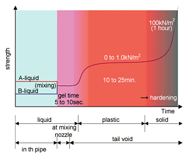
Early Backfill Strength Graph
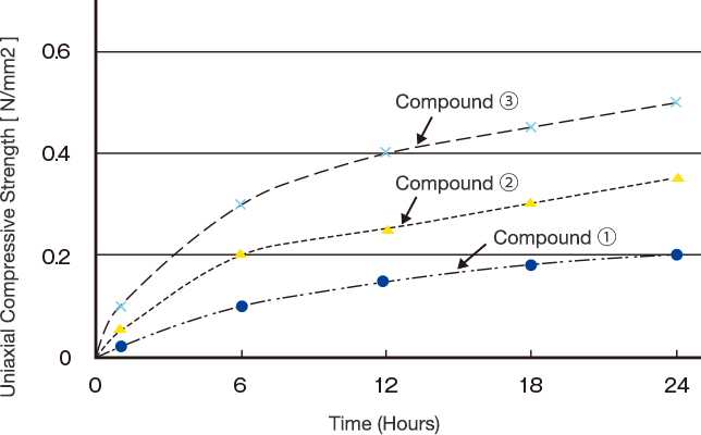
① Component A properties: Flow value: 400 ± 100 mm
② Component A + B mixed properties: Gel time: within 15 seconds
③ For actual construction, the mix proportions must be thoroughly reviewed in light of the project specifications and site conditions.
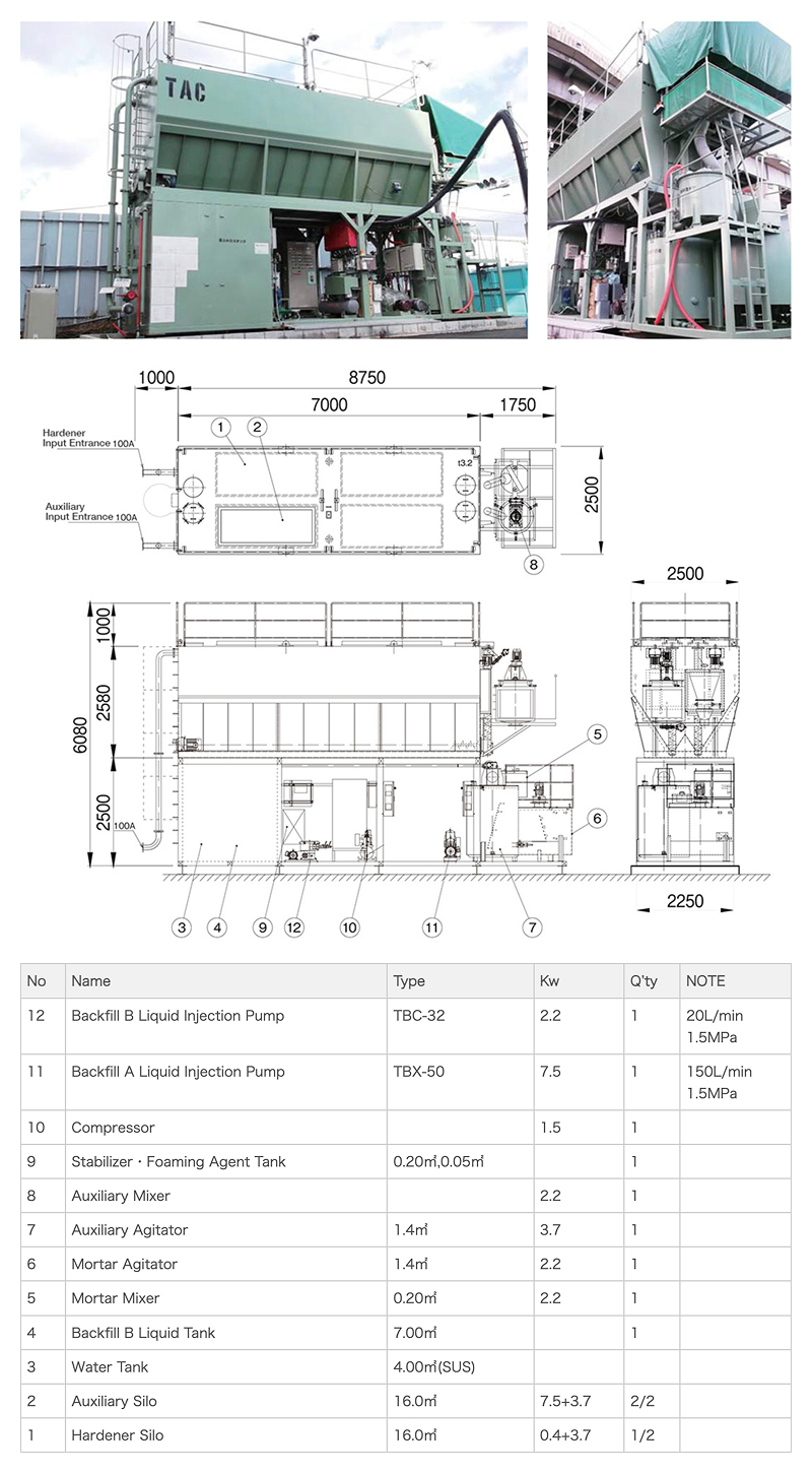
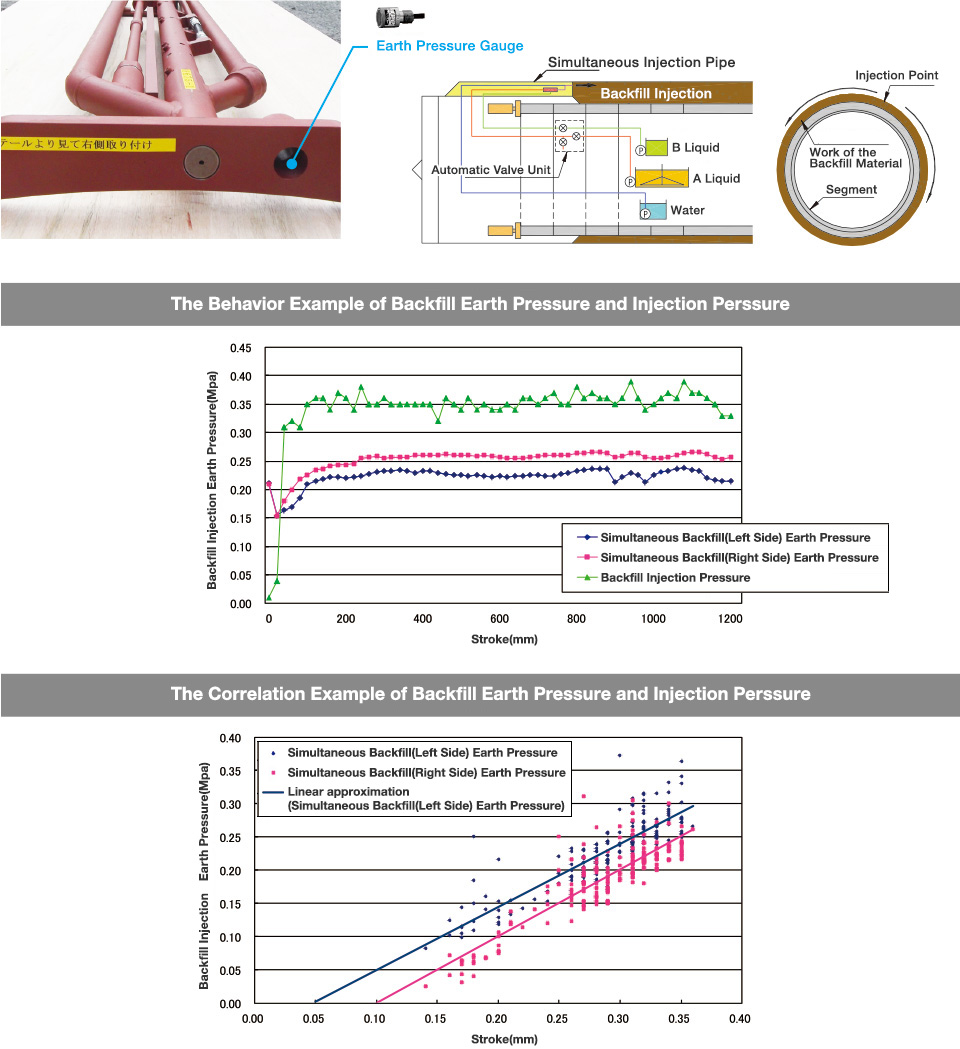
This section introduces the equipment and flow diagrams that support stable backfill grout injection work.
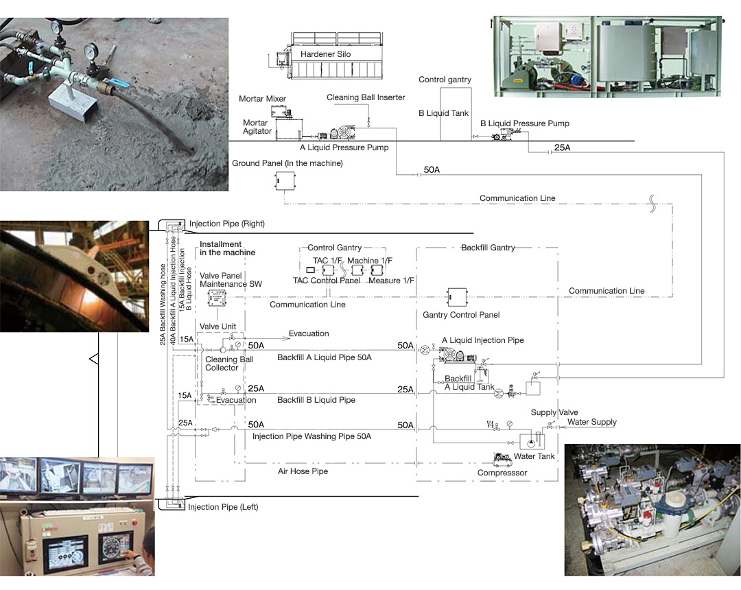
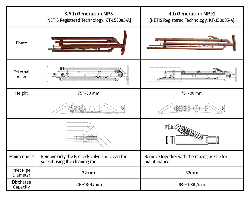
The simultaneous injection pipe is installed at the top of the shield machine and used in the "simultaneous injection method," in which grout is injected immediately into the tail void generated during excavation. Among these, the front-mixing injection pipe incorporates a mixing nozzle for the two components at its tip, enabling injection based on the same principle as injection from the segment inlets. This significantly reduces the risk of blockage troubles.

As a guideline, maintenance for the simultaneous injection pipe is required when the pressure of backfill Component B or the flushing water pressure increases. The rubber tube must be replaced regularly.
In addition, so-called "mortar cholesterol" tends to adhere to the inner surface and joints of the injection pipe, so circulation cleaning with TAC Clean and mechanical cleaning using Kantool tools are effective.

The ETAC Method, developed in 2000, is an injection method that enables the use of two-component plastic backfill materials with a simple pipe-type injection line. The method is highly regarded overseas as an effective means of controlling ground settlement.

TEL:+81-869-84-2069
Phone Hours::Weekdays 9:00–17:00 (JST)
FAX:+81-869-84-3288