
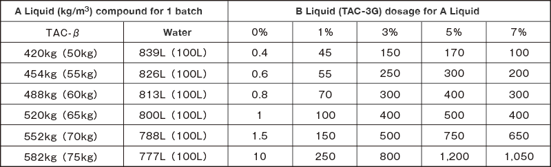
Clay Shock is a highly viscous, plastic-type filling material—approximately 300 to 500 dPa·s—produced by proportionally mixing Clay Sand TAC-β (βⅡ) solution with the special water glass TAC-3G. This construction method utilizes Clay Shock to achieve effective ground conditioning and filling performance.
Features of Clay Shock
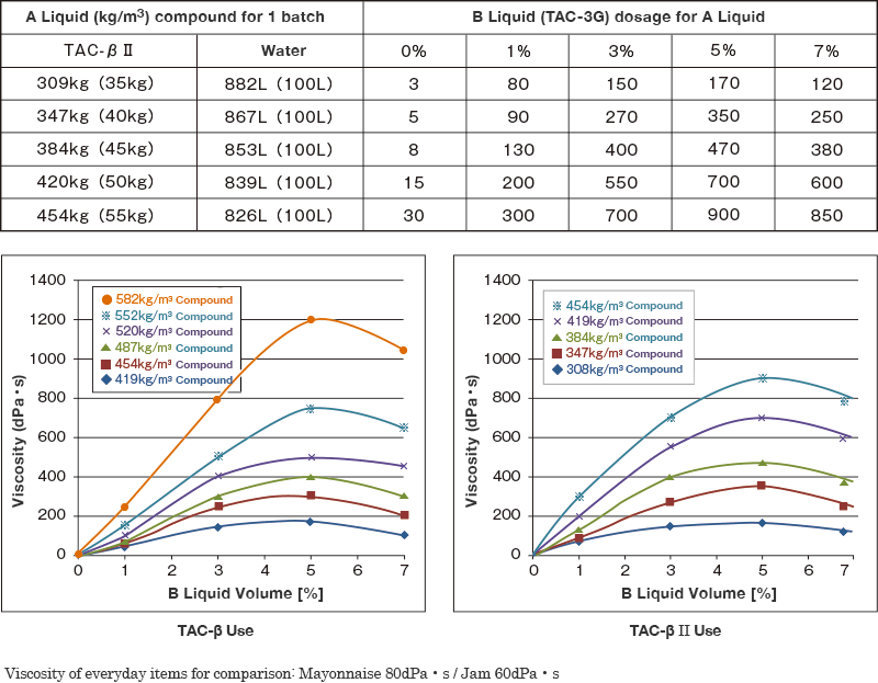
This section introduces the mix proportions and viscosity characteristics of the materials that constitute Clay Shock.
Mix Using TAC-β
| A Liquid (1 m³) | B Liquid | |
|---|---|---|
| Clay Sand | Water | Special Water Glass |
| TAC-β | TAC-3G | |
| 520kg (495kg) | 800L (762 L) | 50L(48L) |
**Values in parentheses indicate the mix proportion per 1.0 m³ of Clay Shock.
Mix Using TAC-βⅡ
| A Liquid (1 m³) | B Liquid | |
|---|---|---|
| Clay Sand | Water | Special Water Glass |
| TAC-β II | TAC-3G | |
| 384kg (366kg) | 853L (812L) | 50L (48L) |
**Values in parentheses indicate the mix proportion per 1.0 m³ of Clay Shock.
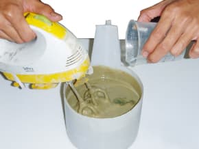
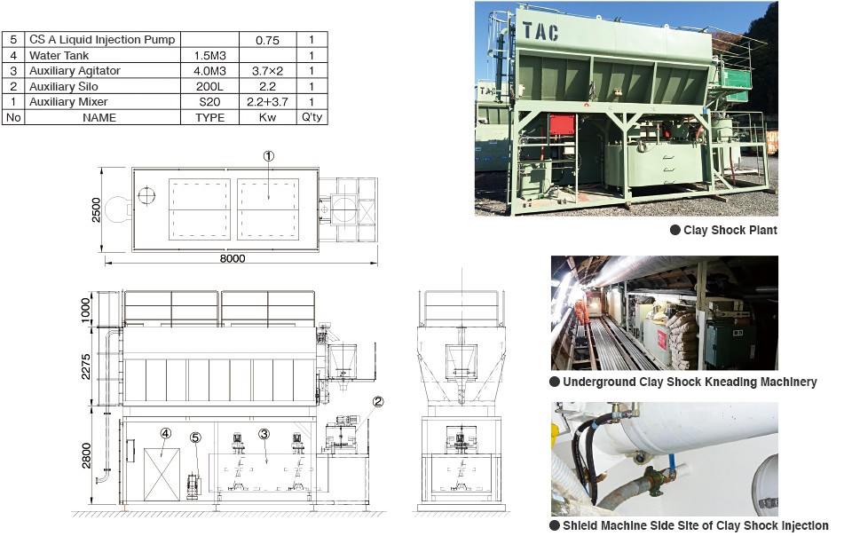
Mixing and Agitation of A and B Liquids
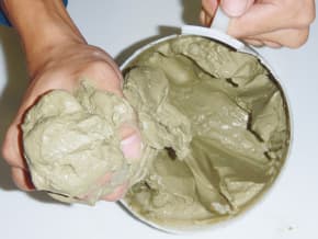
Clay Shock Production
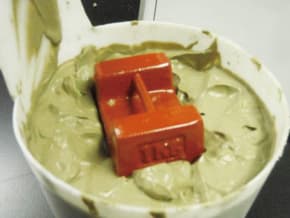
Condition Under 1 kg Weight Loading
(Measured Using a Viscometer Viscosity of Clean Water: 1 cp = 0.01 dPa·s)
Example of Clay Shock Viscosity Measurement (Using TAC-β)
※ Viscosity Unit: dPa·s
Example of Clay Shock Viscosity Measurement (Using TAC-βⅡ)
※ Viscosity Unit: dPa·s
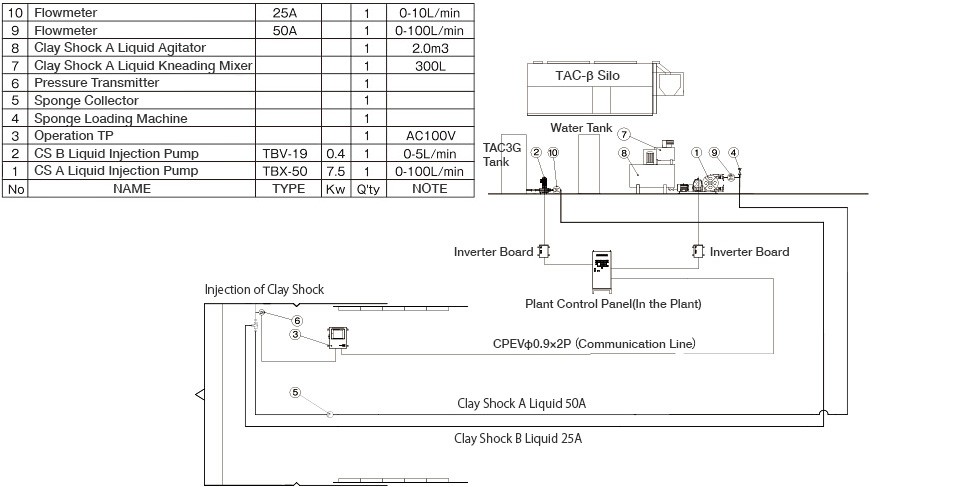
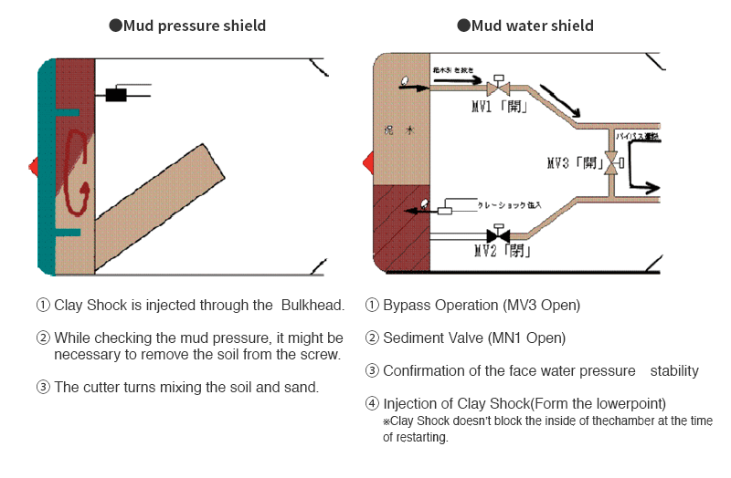
This section introduces the equipment and flow diagram required for Clay Shock injection.
Construction of sharp curves, which requires a high level of technical expertise, has traditionally relied on various auxiliary methods, often involving ground improvement work from the surface.
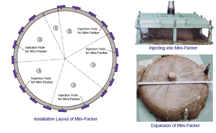
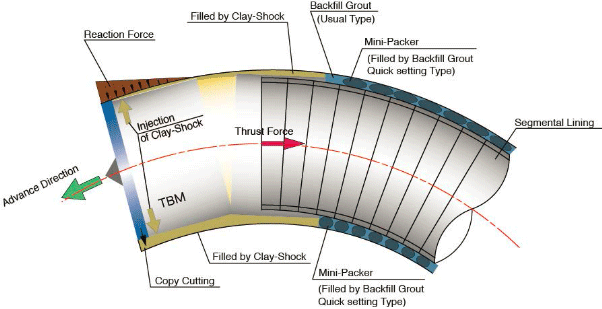
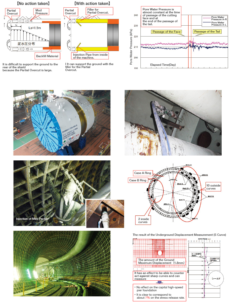
The Clay Shock Mini-Packer Method, which utilizes Clay Shock, enables reliable excavation even under such restrictive conditions while minimizing the impact on the surrounding environment.
The Mini Packer is a backfill injection bag used for localized backfill injection. It prevents backfill grout from flowing around the outside of the shield machine and helps secure the segments in place.
Here we introduce examples of Clay Shock application under various conditions.
1. Maintaining earth pressure during excavation stoppage of Earth Pressure Balance (EPB) shields
2. Maintaining earth pressure during long-term stoppage of slurry and EPB shields
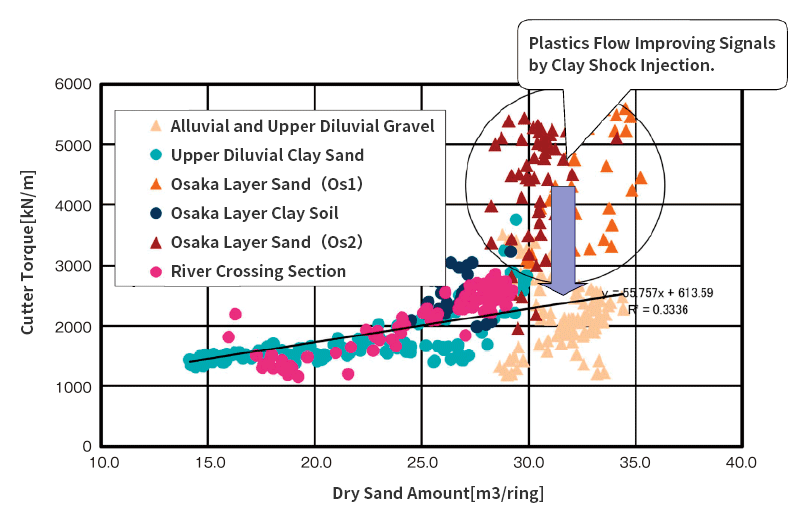
Relationship Between Dry Sand Content and Cutter Torque
TEL:+81-869-84-2069
Phone Hours::Weekdays 9:00–17:00 (JST)
FAX:+81-869-84-3288